
Detection Tubing Design in Micro Fire Suppression Systems: Material Behavior, Thermal Logic, and System Reliability
Introduction: Why Detection Tubing Is a Critical Design Element
In micro fire suppression systems, detection tubing is often visually understated—thin, flexible, and mechanically simple. Yet from a system architecture standpoint, it is the most critical sensing element in the entire suppression chain. Detection tubing is not merely a trigger; it is the primary interface between a developing fire and the suppression system’s response logic. Its behavior governs how quickly a fire is recognized, where the system responds, and whether suppression is initiated with sufficient precision to be effective.
Unlike room-level fire protection, where detection and suppression are often decoupled and mediated by control logic, micro-enclosure systems rely on extremely short detection-to-discharge timelines. Fires inside cabinets, control panels, and equipment housings escalate rapidly due to confined heat buildup, concentrated fuel sources, and limited dissipation pathways. In this context, the thermal response characteristics of detection tubing define system reliability more directly than any downstream component.
For both Direct Low-Pressure (DLP) and Indirect Low-Pressure (ILP) architectures, detection tubing functions as the system’s nervous system. It continuously samples the enclosure’s thermal environment along its entire length, translating localized heat anomalies into mechanical action. Understanding why tubing behaves the way it does—materially, thermally, and mechanically—is essential for designing systems that respond neither too late nor unnecessarily early. This article examines detection tubing not as a commodity component, but as a deliberate engineering decision that underpins the performance of micro fire suppression systems.
Conceptual Role of Detection Tubing in Micro Suppression Systems
Detection tubing operates as a continuous linear heat detector. Unlike point detectors, which measure conditions at a single fixed location, tubing monitors temperature along its entire routed path. Every millimeter of tubing is an active sensing element. This distributed sensing capability is particularly well-suited to enclosures where fire ignition points are uncertain, spatially constrained, or obscured by equipment geometry.
In micro-enclosures, fires rarely originate in predictable, open locations. They typically begin at connection points, overloaded conductors, failing components, or within dense wiring assemblies. Point detectors may be thermally isolated from these locations, delayed by airflow patterns, or shielded by physical obstructions. Detection tubing, by contrast, can be routed in close proximity to likely ignition zones, ensuring that the earliest thermal signature of a fire is captured without requiring precise prediction of its origin.
The tubing’s role is not to measure temperature in an analytical sense, but to respond decisively when a defined thermal threshold is exceeded. It does not provide temperature values or trends; instead, it converts a localized heat event into a binary mechanical outcome. This simplicity is intentional. In micro suppression, speed and certainty are prioritized over interpretive logic. Detection tubing excels in this role because it eliminates intermediary decision layers between fire exposure and system actuation.
Material Science Behind Detection Tubing
At the core of detection tubing performance is polymer behavior under heat. Detection tubing is manufactured from engineered polymers selected for predictable softening and failure characteristics when exposed to elevated temperatures. These materials are not chosen to melt, burn, or degrade gradually; they are designed to lose mechanical integrity rapidly and consistently once a defined thermal condition is reached.
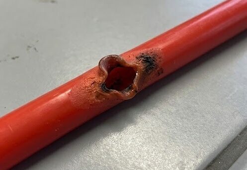
As temperature increases, the polymer chains within the tubing undergo softening as intermolecular forces weaken. This softening reduces the tubing’s ability to withstand internal pressure. Importantly, the tubing does not rupture because it reaches a melting point in the conventional sense. Instead, it fails because its tensile strength decreases below the stress imposed by the pressurized internal environment.
This distinction matters. A melting material would deform unpredictably, potentially collapsing or sealing rather than opening. Detection tubing, by contrast, is engineered to fail by rupture, creating an opening through which pressure is released. The rupture is abrupt, localized, and mechanically decisive. This ensures that system activation is clear and irreversible once the thermal threshold is exceeded.
Temperature thresholds associated with tubing are not arbitrary ratings but expressions of design intent. They represent a balance between avoiding nuisance activation under normal operating conditions and ensuring rapid response to genuine fire events. The selected threshold reflects expected ambient temperatures, equipment heat output, and acceptable safety margins, not merely material limits.
Burst Characteristics and Thermal Response Logic
A common misconception is that detection tubing behaves like a fuse—rupturing at a predetermined point once a global condition is met. In reality, tubing rupture is governed by thermal gradients, not absolute enclosure temperature. The tubing fails at the location where thermal exposure is greatest, because that segment experiences the most rapid loss of mechanical strength.
This behavior gives detection tubing a unique spatial intelligence. It does not simply detect that a fire exists; it identifies where thermal intensity is highest. In DLP systems, this directly determines the discharge location. In ILP systems, it determines the initiation point for system actuation.
Tubing length and routing influence response time but not rupture logic. Longer tubing does not delay activation unless it increases the distance between the tubing and the heat source. Response time is governed primarily by proximity, heat flux, and airflow conditions. Tubing routed close to likely ignition points will respond more rapidly than tubing routed generically around an enclosure perimeter.
Proximity must be understood thermally, not visually. A tube may appear close to a component but be shielded by airflow or metal barriers that divert heat. Conversely, tubing placed higher in an enclosure may experience faster activation due to heat rise, even if physically farther from the ignition source. Effective design accounts for heat movement, not just component layout.
Detection Tubing in Direct Low-Pressure (DLP) Architectures
In Direct Low-Pressure architectures, detection tubing performs a dual function: it senses the fire and serves as the discharge pathway for the suppression agent. This convergence of roles amplifies the importance of tubing behavior, because rupture characteristics directly influence both detection and suppression effectiveness.
When tubing ruptures in a DLP system, the opening created becomes the discharge orifice. The size, shape, and orientation of that rupture affect how the agent exits and interacts with the fire. Because the rupture occurs at the point of highest thermal exposure, discharge is inherently localized to the fire’s origin. This makes DLP systems highly effective for small, clearly defined risks where precise agent delivery is desired.
However, this architecture also places strict demands on tubing placement. If tubing is routed too far from potential ignition points, detection may be delayed. If it is routed in thermally sheltered areas, rupture may occur at a less effective location. Because there are no secondary nozzles or distribution mechanisms, tubing placement precision is inseparable from suppression performance.
From a tubing perspective, DLP systems prioritize immediacy and certainty over coverage breadth. The tubing must be treated as both sensor and actuator, with little tolerance for ambiguity in how it will respond under fire conditions.
Detection Tubing in Indirect Low-Pressure (ILP) Architectures
In Indirect Low-Pressure systems, detection tubing functions solely as a pneumatic trigger. Its rupture does not define where suppression agent is delivered, only when the system transitions from standby to discharge. This separation of detection and distribution fundamentally changes how tubing is designed and evaluated.
Because discharge occurs through dedicated nozzles, tubing placement in ILP systems can prioritize reliable detection rather than precise discharge targeting. Tubing may be routed where heat accumulation is most likely, such as near enclosure ceilings or exhaust paths, even if those locations are not optimal for agent discharge.
Rupture in an ILP system initiates valve actuation, allowing the stored agent to flow through a predefined distribution network. This means that detection timing influences suppression effectiveness, but rupture location does not directly affect agent placement. As a result, ILP systems are more tolerant of tubing placement variability and are better suited to larger or more complex enclosures.
Detection strategy in ILP systems can also be layered. Tubing may serve as a final, mechanical confirmation of fire conditions, complementing electronic or aspirated detection methods that provide earlier warning. In this role, tubing acts as a deterministic safeguard against false positives, ensuring that suppression occurs only when thermal conditions warrant it.
Environmental and Enclosure Influences on Tubing Performance
Detection tubing does not operate in isolation; its behavior is influenced by the enclosure environment in which it is installed. Airflow, ambient temperature, vibration, and enclosure layout all affect how heat is transferred to the tubing and how quickly rupture occurs.
Internal cooling fans can delay activation by removing heat from tubing surfaces, particularly in high-velocity airflow zones. Conversely, heat stratification can accelerate activation in upper regions of an enclosure, even if the fire originates lower down. Component shielding can create thermal shadows, preventing tubing from experiencing sufficient heat despite proximity to a fire source.
Long-term environmental exposure also matters. Repeated thermal cycling can gradually alter polymer properties, leading to changes in flexibility or brittleness. Chemical contaminants, oils, or dust accumulation can affect heat transfer characteristics. Mechanical vibration can introduce micro-damage over time, increasing susceptibility to unintended rupture or reducing responsiveness.
These factors reinforce the need to view tubing as an environmental sensor whose performance evolves over the system’s lifecycle, not a static component frozen at commissioning.
Reliability, Failure Modes, and False Activation Considerations
From a reliability standpoint, detection tubing is remarkably robust. Its simplicity eliminates many failure modes associated with electronic detection systems. However, failures can occur if tubing is mechanically damaged, improperly routed, or exposed to conditions outside its design envelope.
False activation is rare and typically results from abnormal thermal exposure rather than spontaneous material failure. Examples include localized overheating unrelated to fire, such as failed cooling systems or external heat sources introduced after installation. Mechanical damage that compromises tubing integrity can also lead to pressure loss, though this is more likely to result in system trouble signals than unintended discharge.
Failure tolerance differs between architectures. In DLP systems, tubing damage directly compromises suppression capability. In ILP systems, tubing failure may prevent actuation but does not affect agent distribution hardware. This distinction influences how redundancy and supervision are approached in system design.
Detection Tubing as Part of a Layered Detection Strategy
Detection tubing does not need to operate alone to be effective. In many systems, it functions alongside smoke detection, aspirated sampling, or electronic thermal sensors. In these configurations, tubing provides a mechanical confirmation layer that validates fire conditions before suppression is initiated.
In simple enclosures, tubing alone may be sufficient due to its speed and reliability. In high-value or high-consequence environments, redundancy improves confidence and reduces the likelihood of unnecessary discharge. Importantly, layering detection does not change tubing’s role; it reinforces it by ensuring that suppression decisions are grounded in multiple, complementary indicators.
Relationship to System Design and Other Spoke Topics
Detection tubing behavior directly influences other aspects of system design. Nozzle placement strategies depend on whether tubing rupture defines discharge location or merely triggers distribution. Clean agent selection affects discharge dynamics following tubing activation. Cabinet fire dynamics determine where tubing should be exposed to heat earliest. Control panels and releasing logic must account for tubing actuation characteristics when integrating mechanical and electronic detection.
As such, detection tubing is foundational. Understanding its behavior provides the context needed to engage meaningfully with other design variables rather than treating them as isolated decisions.
Closing Perspective
Detection tubing is not a passive accessory in micro fire suppression systems; it is an active, defining design element. Its material behavior, thermal response logic, and interaction with enclosure conditions determine whether suppression occurs quickly, accurately, and reliably. Treating tubing as a commodity risks undermining the entire system architecture.
By understanding why detection tubing behaves as it does—and how that behavior differs between DLP and ILP architectures—engineers and designers can make informed decisions that align detection strategy with suppression objectives. In micro-enclosure fire protection, reliability begins with sensing. Detection tubing is where that sensing truly starts.